Mold making can be done with rigid or soft materials and really only has three principals, all of which are inextricably related:
- Release agents: Prevent bonding
- Parting lines: Subdivide molds into removable pieces
- Draft angles: Allow pieces to be assembled/ dissembled in order
Flexible polyurethane mold with rigid "mother mold".
Molds can exploit material properties through their own geometry.
Molds can be the best (or only) way to achieve certain material characteristics.
Molding and casting materials are interchangeable. Some molds are one time use (waste molds), and others are for multiples (production molds).
Sources:
If anyone is a fan of this text editor, you may want to use it to work with Arduino instead of the default IDE.
Here's a link that can get you started:
https://github.com/Robot-Will/Stino
Xbee w/ Arduino Fio
Xbee is great but can be a little fussy to program (another tutorial). The Arduino Fio operates as a compact, xBee ready dev board. With a few handy tools you can be up and running (wireless reprogramming! and wireless serial) from Fio to Fio or from Fio to your PC.
Fio page
xBee page
The xBee is a little radio transmitter and receiver and needs to have a 'station' to broadcast from and tuned into the channel that's broadcasting.
Here we will learn:
- ONE way to configure the xBees.
- Use them to wirelessly program the Arduino.
- See an example of serial wireless control.
A nice way to do this is with the xBee Explorer. It configures the station and the channel between two (or more) xBees.
xBee Explorer page
The explorer plugs into the USB port on you computer. One xBee radio at a time can plug into the Explorer for configuration.
Here's the best part. There is a config Tool made in Processing to do this very easily. Source Code HERE.
Configuration parameters:
Serial Port: USB (where the Explorer is)
Mode: For Point-to-Point (P2P) you have one xBee Programming Radio, the other xBee "Arduino Fio Radio". (But they'll work from Fio to Fio).
Baud Rate is based on the board's chip. Most Fios have an ATmega328 so the baud rate is 57600.
PAN ID: Personal Area Network: Should be the same between both (or several) xBees.
MY ID: The address of each xBee, never the same, starting with '0', then '1' , ect.
DL ID: Destination address (MY ID and DL ID should be inverted to get two-way serial communication.)
Example:
Plug xBee 0 into the Explorer and enter these values through the configuration tool:
- Serial Port: USB
- Programming radio
- Baud Rate: 57600
- PAN ID: 1111
- MY ID: 0000
- DL ID: 0001
Then click the "Configure" button. At the bottom you should momentarily see:
"Configured Successfully".
-------------
Plug xBee 1 into the Explorer and enter these values through the configuration tool:
- Serial Port: USB
- Arduino Fio radio
- Baud Rate: 57600
- PAN ID: 1111
- MY ID: 0001
- DL ID: 0000
Then click the "Configure" button. At the bottom you should momentarily see:
"Configured Successfully".
Now serial commands can be sent from 0 to 1, 0 to 1. This can be from your computer, via the Explorer, to another micro controller or from Fio with xBee 0 to Fio with xBee 1, etc.
To load a sketch onto the Fio, you do so wirelessly. xBee 0, via the Explorer, can upload to the Fio with xBee 1 through the Arduino IDE.
Example Code HERE.
Example Code HERE.
Note: Change the baud rate through the serial monitor window, bottom right, to 57600. Under Tools > Board > DO NOT SET TO FIO! Set the board to "Arduino Pro or Pro Mini (3.3v, 8MHz) w/ ATmega328.
---------------------
Latest: http://www.nordicsemi.com/eng/News/ULP-Wireless-Update/Finger-tip-sized-wireless-module-boasts-Arduino-compatibility
For a good, thorough start check out this link:
http://erion.elmasllari.com/in-the-trenches-with-xbee-resources-and-tips/
and here for X-CTU (Windows/PC):
http://www.ladyada.net/make/xbee/configure.html
xBee AT:
https://dlnmh9ip6v2uc.cloudfront.net/learn/materials/29/22AT%20Commands.pdf
xBee API:
http://code.google.com/p/xbee-api/
"Making Things Talk: Second Addtion" by Tom Igoe = free goodness full of xBee tutorials, examples and projects.
http://www.proalias.com/books/Making_Things_Talk_Second_Edition.pdf
Hooking up xBee with a stranger:
http://answers.oreilly.com/topic/2458-how-to-connect-an-arduino-to-an-xbee-radio/
Rhino to Illustrator :: Laser Cut in CodeLab
Here is a step by step on how to use Rhino and Adobe Illustrator to make laser cut files.
Starting with SOFTWARE
Open your Rhino file and work in the TOP view.
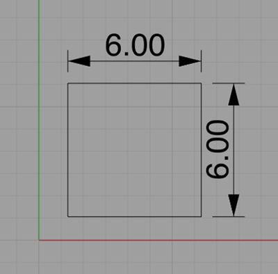
If your material size is smaller than the bed of the laser cutter (24"x18"), you should start by making a reference line the same size as you material. For example, 6"x 6".
Nesting: The term nesting is common in digital fabrication. You need to make sure all of your new laser babies will fit into your limited material nursery.
Conserve Material!: In the event your aren't going to use the whole piece, you should move parts close to the edges. This leaves lots of good material for the next project. For reason's you'll see later, NEST everything you have in the top-left corner of your material outline.
Select the lines to be cut or etched, not the material outilne. From the menu line choose File>Export Selected.
In the AI Export Options window make sure to click "Preserve model scale" and that your units match 1-to-1. Again, click "Export".
***The CodeLab's PC for laser cutting is not networked. Save and transfer your file with a USB jump drive.
HARDWARE
This is the CodeLab's Epilog Lasertastic 6000. The power button is on the left side. It will do a calibration routine every time it is restarted. It is flanked by two of its good friends...
This part is important: The friend on the left is a tank of compressed Nitrogen. It is non-toxic (you think that's "air" you're breathing now?) It's also non-flamable and keeps the laser bathed in fire suppressant, which is nice.
NOTE: LASER CUTTERS CAN CATCH FIRE AND ARE NEVER TO BE LEFT UNATTENDED WHILE CUTTING. THERE IS A FIRE EXTINGUISHER TO THE LEFT OF THE NITROGEN.
The nitrogen tank should be closed every time you're finished. You do this buy turning the metal, star-shaped knob to the right ( that's clockwise if you're looking down on it). It should be opened every time you're about to begin cutting, by turning the same knob left (counter-clockwise). When you do so you should see two things:
1) The gauge on the right should move clockwise. If it doesn't, the tank is empty and you should not use the laser cutter, and you should let someone know to order more.
2) The gauge on the left should read about 5 psi. That is the inside set of numbers. If it is less, or more, adjust it by turning the large black knob (the one pointing at you) until it reads 5 psi.
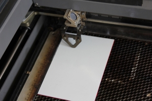
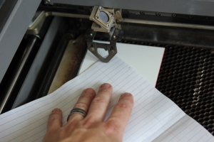
Slide a normal piece of paper between the focus gauge and your material. If it slips through easily, use the UP key to raise the bed. When it just begins to get pinched between the gage and your material, you've got it! If it doesn't slide, use the DOWN and UP keys until it's perfect.
REMEMBER TO REPLACE THE FOCUS GAUGE so that it's pointing up. Close the lid. Go to the computer just outside the laser cutter room...
Back to SOFTWARE
On the PC just outside the laser cutter room, open your .ai file in Illustrator . Set the ARTBOARD SIZE (File>Document Setup>Artboard...) to 23.5"w x 17.5"h. (Why 1/2" shorter than the bed size? To keep from accidentally sending the laser past its safe limits.)
Move your geometry to the top left corner of the artboard. Select all of you geometry, move it to the top/left corner of the artboard and set the STROKE to .0001". If you don't it won't cut.
From the menu bar select File > print... Make sure you see something like this. Note the Printer: Epilog Engraver, Size: Defined by Driver, the Placement of your geometry, and the window which should show your geometry packed in the top-left corner of the box.
Click on SETUP at the bottom-left of the screen.
In the next window (no image), click on PREFERENCES to bring up the Printing Preferences window.
In the GENERAL tab, select VECTOR (that's cutting through). You'll see sliders to adjust Speed, Power, Frequency. Check the box to automatically set Frequency.
You'll find a couple of ways to know how to set speed and power:
1) You may see a box of sample cuts next to the computer with settings written on the specific sample. You may try those. To do so, move the sliders to the corresponding values. Click OK. This will take you back to the PRINT screen (below).
2) See the next image, ADVANCED tab...
2) In the ADVANCED tab, you may see pre-set files for specific materials. If you see one that matches your material and cutting type, try it. Select it from the list, click LOAD, then click OK. This will take you back to the PRINT screen (below).
and, finally...HARDWARE
Find your file on the keypad screen. You may need to scroll through other jobs. To do so, press the JOB key, then use the UP and DOWN keys. Now there are two things to check before you get started... Gas: Check! Exhaust: Check!
Press the GO key! Don't stare at the laser beam! The program will run. When it's done, it will say "BEEP". Give it just a few seconds to clear the air and lift the lid, check your part...
1) Perfection. You cut out your parts in a clean an elegant way. Good job.
2)You thought you cut out your parts. You can see the shapes cut in your material, but it didn't go all the way through. DO NOT MOVE THE MATERIAL! Run the same file again and check it carefully when finished.
3) Crap! You didn't set off the fire alarm but you burned away 1/4" of material on either side of your line. Change your power and speed settings in the GENERAL tab of the Epilog software in a calculated way. Resend the new settings.
4) You just set off the fire alarm and are stopping to save Zack's camera and computer before you exit the building.
Most of these issues can be avoided by testing settings FIRST. I always do this. Every time. It may seem slower, until you've wasted a sheet of material and are off to get more.
________________________________________
Arduino Basics:getting started
If you're having trouble loading sketches (usually marked by the lack of a "usb" serial port for upload) you may need THIS driver. Install it, restart Arduino, and you should be off. Thanks to Chin Wei for providing this.
The Root Code:How It's Made
Learning from Arduino.cc:
Must see...
Reference: What is the Arduino Language?
Learning: Show me what is possible and how!
00000010000001000000100001111
Tutorials on Lady Ada. Recommended (how little Zacky learned!)
http://www.ladyada.net/learn/arduino/
Tutorials from SparkFun. Also Recommended. This set makes good use of many of the components in your starter kits.
From the link below, hover over the ARDX and find links to circuits 1-11...
http://www.oomlout.com/oom.php/products/ardx/circ-01
The PDF below has an example of each of the basic functions of Arduino for interaction. Copy and paste code between the dashed lines, for each sketch.
Download PDF
_________________________________________
Learn to Laser Cut in dFab:
On 9/12 we will be visiting dFab, CMU's fully equipped digital fabrication lab in the basement of MMCH.
In preparation please see dFab Policies and Procedures.
In addition you can review the Rhino-to-Epilog** laser cutting tutorial below:
**For dFab, you do not need to export files to Adobe Illustrator.
Rhino-to-Epilog Laser by dFab director P.Zach Ali
What is TOLERANCE?
Definition 5 on Wikipedia is what we need. The space between two interfacing parts, essentially.
What is KERF?
Dictionary meaning 2 explains its the space or material removed in the process of cutting.
A laser has a kerf, though it is tiny. It may range from .005" - .008". Pretty huge. It's best to know before you plan a well crafted project.
Zach Ali says, "Our lasers have a .001 " kerf!
A friction fit is a connection between two parts that is maintained by the exactness of their articulation. In general, you need around .005" between two parts, to fit them together in a way that will hold without external fasteners like adhesives. The CAD/CAM workflow is more than capable of this exactitude. Try it out.
Hint. Test first, then build.
__________________________________________
Rhino Workshop 2: Basic 3D for Fabrication
Class Reference File: mtiRhino2
- Extrude Curve
- Cap Planar Holes
- Surface menu: revolve, sweep 1 rail, extrude curve, loft
- Solids menu: extrude planar curve, pipe, tube, cap planar holes (primitives: box, sphere, etc...)
- Boolean operations: Union, Difference, Split
Rhino Workshop 1: 2D for Fabrication
Mac users can download Rhino 5 (beta) here: http://mac.rhino3d.com .
Fill out the application and you'll get a download link shortly...
Three ways to learn more as you continue:
- Under the HELP menu inside Rhino you can links to free tutorials: Best value (This is how everyone learns it!)
- YouTube has an assorted (but less organized) list of video tutorials.
- Very organized but for a small fee, http://www.lynda.com/Rhino-training-tutorials/302-0.html . Lynda.com is good if you're looking for step by step lessons.
Class Reference File: mtiRhino1
2D Topics and Keywords:
- units / grid: under file>>settings (Mac) or type "units", enter (Mac/PC)
- navigation: middle mouse roller, right mouse button, +shift, +control
- command line: reset under Rhinoceros>>preferences>>Legacy>>check both boxes
- selecting: left mouse button, click or drag box
- Snaps/Osnaps:bottom of the window, check box on/off
- curves: polylines, control point lines: under curves menu, in toolbox
- points on/off: under edit>>control points>>on/off
- circles, squares, polygons: under curves menu, in toolbox
- trim / join/ explode: under edit menu, in toolbox
- transforms: scale / rotate:under transform menu
- dimensions: linear, aligned, radii: under dimensions menu
- offset: under curve menu, type "offset", enter
- export to Adobe Illustrator: select objects to export, File menu>>export selected, type of file == .ai
Below are lots of links to further learning resources:
Arduino: Arduino.cc is the hub of Arduino on the web. You can find code, forum discussions, tutorials, products, and the entire API here.
http://arduino.cc
dFab: The best of digital fabrication ON CAMPUS. Here you'll find resources that are mainly available only to students in Architecture programs and courses. This includes excellent tutorials on local software and hardware. This is a MUST SEE!
http://cmu-dfab.org
Adafruit: This is one of the first and BEST sources for DIY interaction and Arduino stuff. It's a great store so you'll find it on the purchase page. But it was the place where this all started (for Zack). This is an extensive site, but start here for more basic Arduino lessons.
http://learn.adafruit.com/category/learn-arduino
How to use libraries: http://learn.adafruit.com/adafruit-all-about-arduino-libraries-install-use
Instructables: This site has hundreds, maybe thousands of DIY and professional project examples with steps on how to do it yourself. Interaction design and strawberry shortcake in one place!
http://www.instructables.com
SmartSurfaces: This is a multidisciplinary think tank in its 5th year and developed by friends at the University of Michigan. Inside there are links to dozens of resources related to interaction design, digital fabrication, mechanical engineering and architecture. We are using this link with the expressed permission of its creators! Take a look around...
http://www.smartsurfaces.net/Home
motor heads go HERE: http://www.smartsurfaces.net/electromechanics
Flying Pig [Mechanics!] This a good place to find different kinds of mechanical assemblies with explanations and some kits and parts. And it British!
http://www.flying-pig.co.uk
Processing: This is the graphic counterpart to Arduino. Here you can find all the stuff for Processing including TONS of useful examples and free code.
http://www.openprocessing.org
Eagle and Fritzing: When Arduino went viral, more and more people began designing custom PCBs or Printed Circuit Boards. Not only can you design these boards in several modes, but these services allow you to order your PCB and have it shipped to you.
http://www.cadsoftusa.com/eagle-pcb-design-software/?language=en
http://fritzing.org


By the way, Lynda is free for CMU students:
ReplyDeletehttp://www.cmu.edu/lynda/